
Instrument manual
Nyblcore Guide
Nyblcore is a tiny, open-source sample player built around an ATtiny85. It turns a little audio into jumping, retriggering, stuttering, and stretching patterns. This guide covers playing it, building the kit, and loading your own sounds.
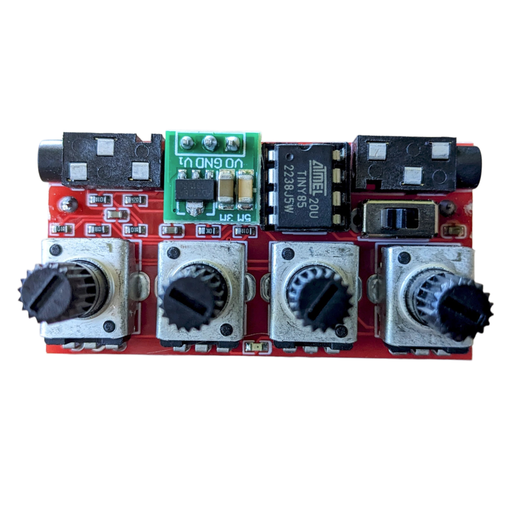
Specifications
- Powered by a single AAA battery, with approximately 5–8 hours of battery life.
- 8 kB of storage for up to 1.2 seconds of 8-bit audio sampled at approximately 4.2 kHz.
- Three multifunction controls for volume, distortion, tempo, and effect probabilities, plus a separate filter knob.
- Load custom audio by programming the ATtiny85 with an Arduino or a USB AVR programmer.
- Open-source firmware, schematics, and board files.
The small memory limits how much audio and how many effects fit on the device. Tempo may not be entirely stable, and there is no external sync. The unpredictability is part of playing Nyblcore.
Quick start
Connect the audio output, insert a AAA battery, and switch Nyblcore on. The selector is the second knob from the left; knobs A and B sit on either side of it.
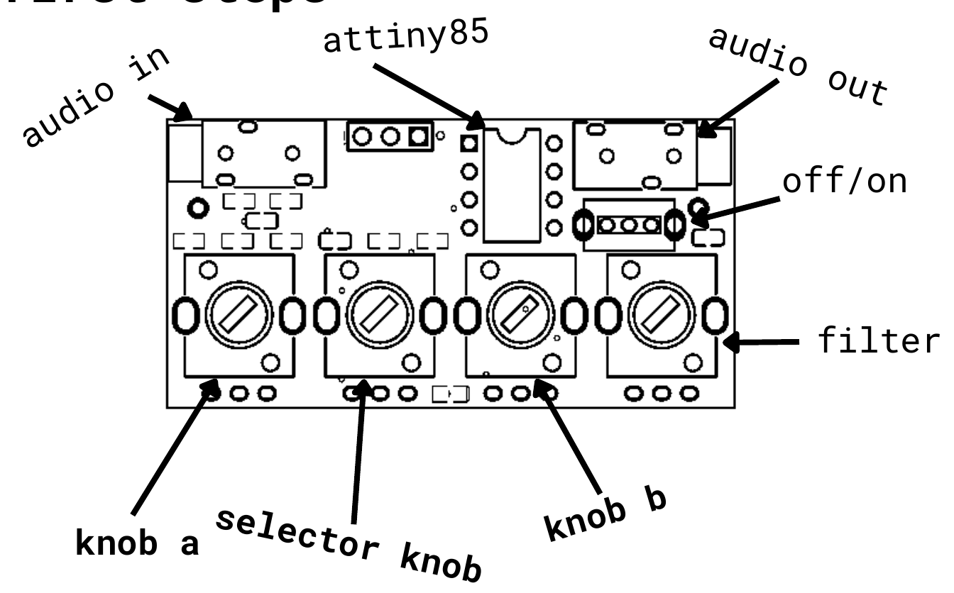
- Turn the selector fully clockwise. Turn both A and B fully counterclockwise to set stretch and stutter probabilities to zero.
- Turn the selector to 12 o’clock. Turn both A and B fully counterclockwise to set jump and retrigger probabilities to zero.
- Turn the selector fully counterclockwise. Turn A up until you hear audio; turning it further adds wavefolding distortion. Adjust B to find a tempo you like.
Return to either effects position and turn A or B up to introduce variations.
Controls and effects
The selector changes what knobs A and B control. The far-right knob controls the filter.
| Selector position | Knob A | Knob B |
|---|---|---|
| Fully counterclockwise | Volume / distortion | Tempo |
| Middle (12 o’clock) | Jump probability | Retrigger probability |
| Fully clockwise | Stretch probability | Stutter probability |
- Jump
- Skips between slices, creating new segments from the original audio.
- Retrigger
- Repeats the same sample.
- Stutter
- Repeats the same sample with an added volume ramp.
- Stretch
- Randomly slows down playback.
The v1.2.0 PDF’s “at a glance” text labels the fully-clockwise B control as jump. It controls stutter, as shown in the PDF’s quick start and the firmware.
Demos
Watch the Nyblcore demo on YouTube.
Example 1: Drum hits
Example 2: Breakbeat
Example 3: Arp
Example 4: Just a sine wave
DIY build
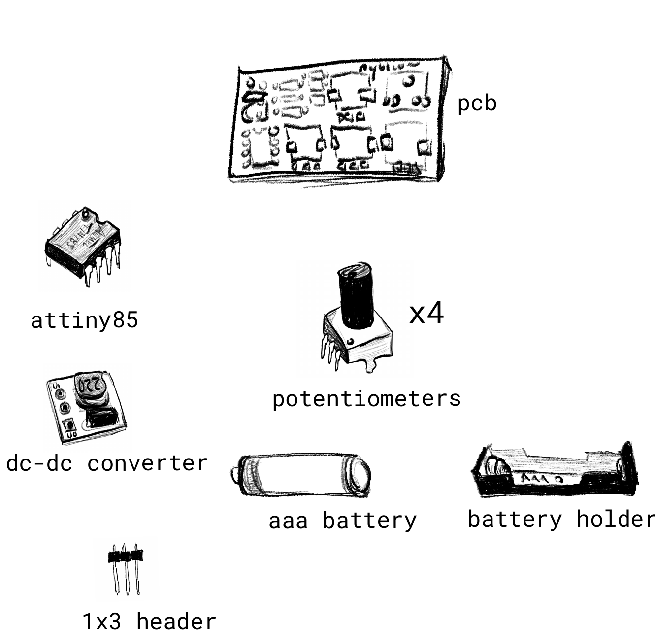
The following inventory and assembly illustrations come from the v1.2.0 manual. Use them alongside the soldering tutorial.
Parts
| Part | Quantity |
|---|---|
| Nyblcore PCB | 1 |
| ATtiny85 | 1 |
| Potentiometers | 4 |
| DC-DC converter | 1 |
| 1 × 3 header | 1 |
| AAA battery holder | 1 |
| AAA battery | 1 |
Assembly
1. DC-DC converter
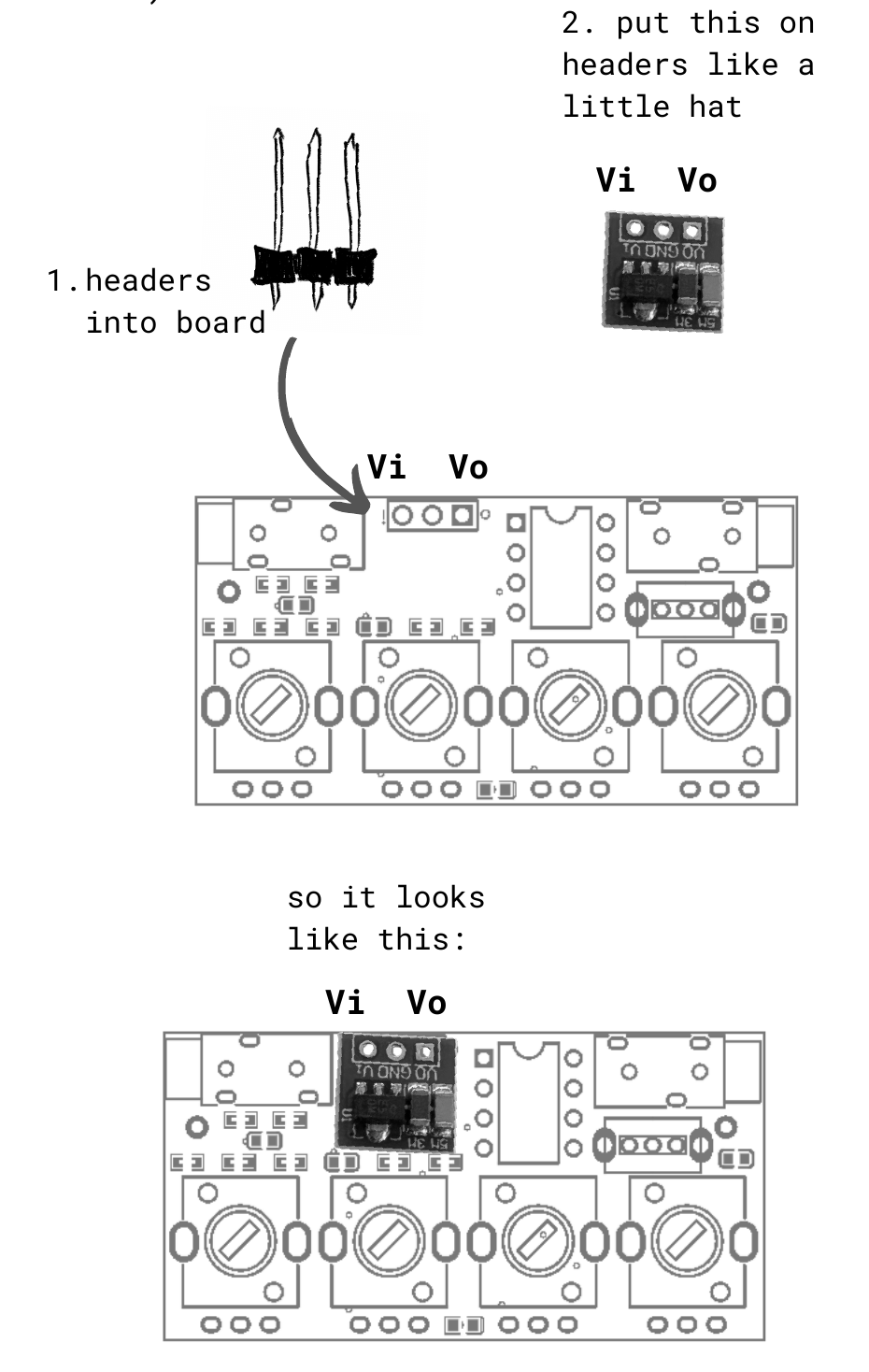
Solder the 1 × 3 header into the PCB with its long legs pointing up. Fit the converter onto the header and solder it. Match the Vi and Vo markings on the converter to those on the board. The manual notes that the converter may sit on the components underneath it.
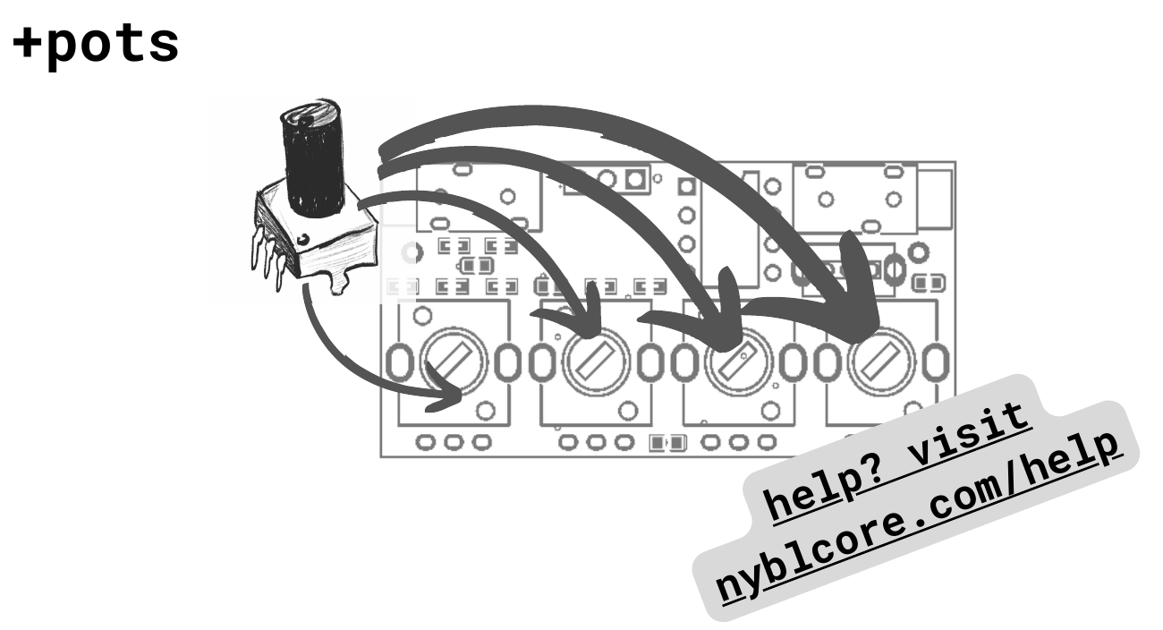
2. Potentiometers
Fit and solder the four potentiometers into the four positions along the front of the board.
3. Battery holder
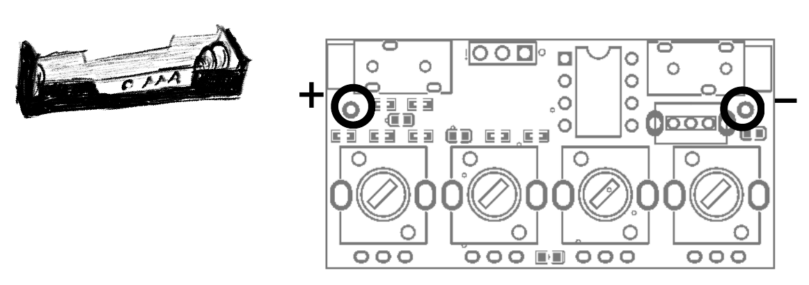
Attach the holder to the back of the board, then solder it from the front. With the board oriented as pictured, the + terminal is on the left. Bend the pins outward to fit; trimming them before insertion makes assembly easier.
4. ATtiny85
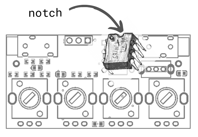
Insert the ATtiny85 with its small notch facing up, toward the top edge of the board in the diagram.
Schematic and board files
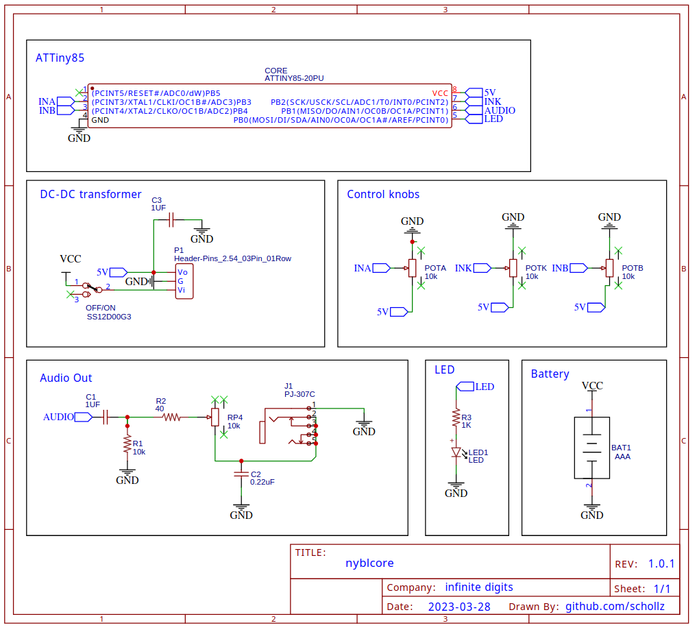
Download the board files from GitHub.
Soldering tutorial
Documentation and source code
Download the original Nyblcore v1.2.0 manual (PDF). The PDF is preserved unchanged, including its printable assembly illustrations.
Source code
Nyblcore is open-source. Find the firmware source, schematics, and Gerber files in the Nyblcore repository.
If you use the public repository to build a Nyblcore, consider sponsoring Zack on GitHub to support more open-source devices and software.
This guide brings together Zackary Scholl’s original Nyblcore page and the v1.2.0 manual. Send questions or feedback to zack@infinitedigits.co, or find @infinitedigits on Instagram.
Original firmware and custom audio
Download the original firmware (.ino) to restore the original sounds, or generate a new sketch from your audio.
Generate firmware from your audio
Opens the audio-to-firmware generator on schollz.com.
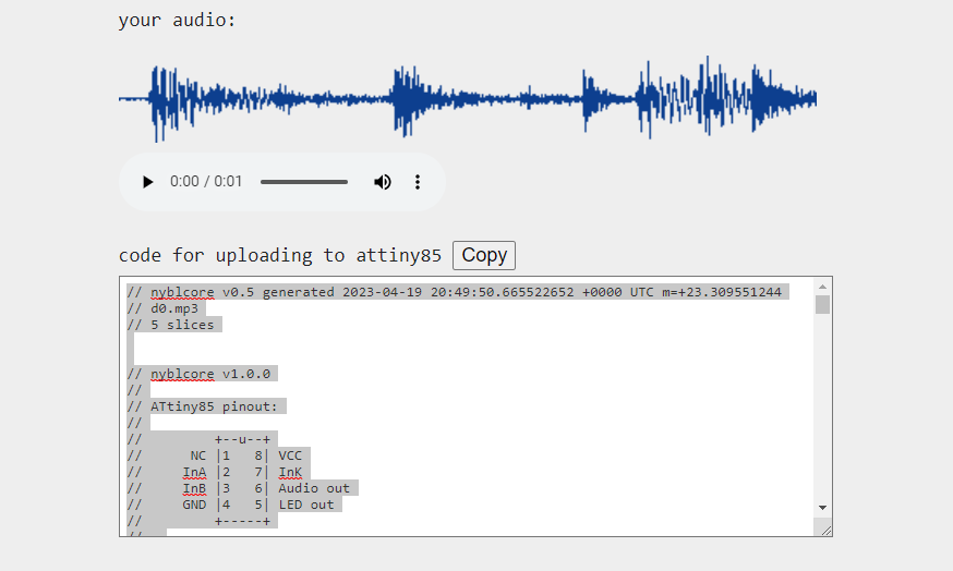
The generator accepts WAV, AIF, OGG, and FLAC files. Choose up to 1.2 seconds of audio, set the slice count for a single file, and optionally add a crossfade. It returns Arduino code containing your samples.
Copy the generated sketch and follow Uploading firmware below. Changing audio means reprogramming the ATtiny85 with an Arduino or USB AVR programmer.
Alternative firmware: Bytebeat
Download the Bytebeat firmware (.ino) from GitHub and upload it using the same programmer workflow. It turns Nyblcore into a synthesizer with approximately 40 formulas.
- Selector fully counterclockwise: knob A changes volume and distortion; knob B selects a Bytebeat formula.
- Selector fully clockwise: knob A selects a parameter in the current formula; knob B changes that parameter’s value.
Bytebeat parameter changes reset when you power-cycle the device.
Uploading firmware
If this is your first upload, complete the programmer setup first.
- Download an original or Bytebeat sketch, or copy the code returned by the audio-to-firmware generator on schollz.com.
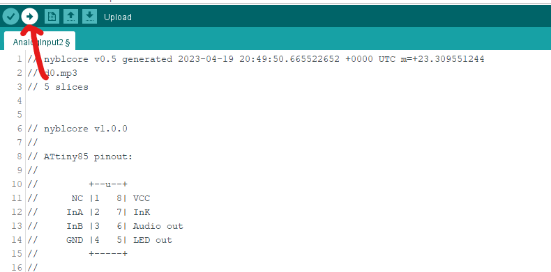
- Open the sketch in the Arduino IDE, or paste the generated code into a new sketch.
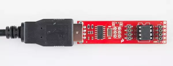
- With Nyblcore switched off, remove its ATtiny85 and place it in your programmer. Connect the programmer to your computer.
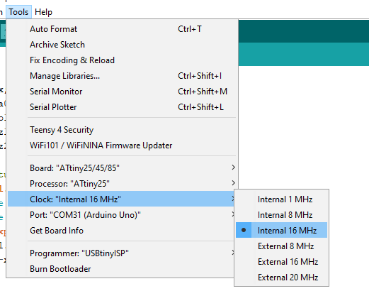
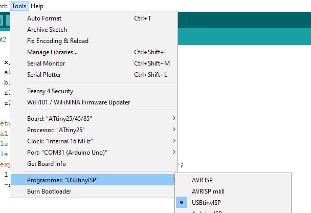
- Check the board, clock, and programmer settings below, then upload the sketch.
- Disconnect the programmer and return the ATtiny85 to Nyblcore, observing the chip’s notch orientation. Switch on to hear the new sounds.
Programmer setup and tools
You need an ATtiny85-compatible USB AVR programmer, such as a USBtinyISP programmer, to change Nyblcore’s firmware or samples.
You can also use an Arduino Uno as a programmer. Follow that method’s programmer setup, but select Internal 16 MHz for Nyblcore rather than 8 MHz.
- Install the Arduino IDE. Windows users may also need the USBtinyISP drivers.
- Open the IDE’s Preferences and add the following URL to Additional Boards Manager URLs:
https://raw.githubusercontent.com/damellis/attiny/ide-1.6.x-boards-manager/package_damellis_attiny_index.json
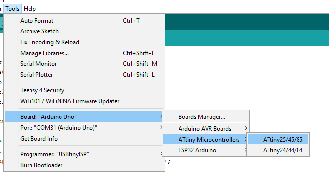
- Install the ATtiny package through Boards Manager, then select Tools → Board → ATtiny Microcontrollers → ATtiny25/45/85 and choose the ATtiny85 processor.
- Select Tools → Clock → Internal 16 MHz.
- For a USBtinyISP programmer, select Tools → Programmer → USBtinyISP.
Return to Uploading firmware to program the chip. If you get stuck, send a message to zack@infinitedigits.co.